Furnace Short Cycling: Time the Sequence Before Replacing Parts
Use burner, blower, thermostat, errorcode, temperaturerise, and pressure evidence to separate airflow limits, ignition failures, venting faults, thermostat problems, and oversizing.
Direct Answer
Use burner, blower, thermostat, errorcode, temperaturerise, and pressure evidence to separate airflow limits, ignition failures, venting faults, thermostat problems, and oversizing.
Quick Checks
- 1Record the control-board fault code before switching power off; a reset can erase useful evidence.
- 2Do not bypass a limit, pressure switch, flame safeguard, panel switch, or other safety device.
- 3Compare measured temperature rise and static pressure with the exact furnace nameplate and installation instructions.
Short Cycling Describes a Pattern, Not a Part
Short answer: A furnace is short cycling when a heating call ends or the burners shut down unusually soon and the pattern repeats before the home reaches its target. Start by timing the thermostat call, inducer, ignition, burner, and blower. Check the filter, open registers, thermostat location, and visible intake/exhaust safely. Gas, flame, venting, high-limit, heat-exchanger, electrical, and internal control work belongs to a qualified technician.
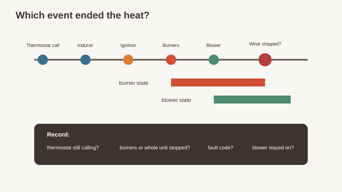
The first question isn't “Which part is bad?” It's “Which event ended the cycle?” A thermostat can stop the call. A furnace safety can stop the burners while the blower keeps running. A failed ignition sequence can end in seconds. An oversized furnace can satisfy the thermostat quickly while operating exactly as wired.
Treat These Signs as Safety Events
Leave the home and follow emergency guidance if a carbon-monoxide alarm sounds or anyone has headache, dizziness, weakness, nausea, confusion, or other possible CO symptoms. Call emergency services or the fuel utility as appropriate. Carbon monoxide is colorless and odorless.
Stop using the furnace and call qualified service for:
- gas or oil odor;
- soot, scorch marks, flame rollout, or melted wiring;
- a damaged, disconnected, corroded, or blocked vent;
- repeated ignition attempts with delayed or rough ignition;
- water affecting electrical or burner compartments;
- a cracked viewing window or cabinet damage;
- a safety switch that someone has bypassed;
- unusual banging, grinding, or electrical arcing.
CPSC advises annual professional inspection of fuel-burning heating systems, chimneys, flues, and vents. Working CO alarms are backup protection, not a diagnostic instrument for furnace combustion.
Write Down the Exact Sequence
Stand at a safe distance. Do not remove burner or blower panels while the furnace operates. Observe lights, sounds, thermostat status, and supply-air behavior.
| Time | Thermostat | Furnace event | Air at register | Indicator/code |
|---|---|---|---|---|
| 0:00 | Heat call begins | Inducer starts | None | Normal startup light |
| 0:20 | Still calling | Ignition and burners | None | No change |
| 1:05 | Still calling | Blower starts | Warming | No change |
| 4:30 | Still calling | Burners stop; blower stays on | Cooler | Limit code appears |
| 7:00 | Still calling | Burners relight | Warming | Code clears |
This example points toward an overheating/limit sequence, not a thermostat ending the call. Possible reasons include restricted airflow, wrong blower setup, excessive firing rate, a dirty heat exchanger or coil, duct restriction, or a faulty control. A technician must test rather than replace the limit switch by guess.
Three cycle patterns that mean different things
Burners die within seconds: flame proving, ignition, gas, grounding, control, or vent-pressure faults are possible.
Burners run several minutes, stop, then relight while the thermostat still calls: high-limit or another safety/airflow problem is possible.
Whole system stops because the thermostat call ends: thermostat location, wiring, control logic, oversizing, or a small active zone may be involved.
Record at least three events. Intermittent faults often appear only during wind, cold, condensate load, or a long recovery.
Preserve the Fault Code
Many furnaces show a status through an LED, display, or thermostat alert. Photograph the code and the legend on the door or manual before resetting power. Note whether the code appeared before or after the burners stopped.
Do not assume a code names the failed part. “Limit open” reports a circuit condition; it doesn't prove the limit is defective. “Pressure switch open” can reflect intake, vent, condensate, inducer, tubing, wind, installation, or switch problems.
Power cycling may clear both the lockout and the evidence. Use a reset only as the manufacturer allows and never repeat it to force unsafe operation.
Safe Homeowner Checks
Filter
Turn the system off as directed. Confirm the filter is the correct size, orientation, and type. A dirty or overly restrictive filter can reduce airflow. Look for collapse, bypass gaps, multiple filters installed in series, and a return grille filter plus cabinet filter that the system wasn't designed to use.
Replace or clean it according to the furnace and filter instructions. Do not run the furnace without a filter as a workaround. The MERV and airflow guide explains why a higher rating isn't useful if the filter area and blower can't support it.
Registers and returns
Open supply registers and return grilles that are intended to be open. Remove furniture, rugs, and storage that block them. Do not close many registers to redirect heat; that can increase duct pressure and reduce airflow across the furnace.
If the problem occurs only with bedroom doors closed, return-air paths and room pressure may matter. A duct technician can measure static pressure and balance rather than guessing at register positions.
Thermostat
Check mode, set point, schedule, batteries, and visible wiring at the thermostat only as its instructions allow. Note nearby supply registers, sun, lamps, kitchens, drafts, or fireplaces that can warm or cool it before the rest of the house.
Smart-thermostat history can show calls, but vendor labels don't replace furnace observations. A thermostat may report “heating” through a furnace safety interruption.
Exterior intake and exhaust
From the ground, look for snow, leaves, nests, or visible damage at direct-vent terminations. Keep the area clear according to the furnace manual. Do not insert tools, pour liquids, cover a terminal, or change its fittings.
Condensate on high-efficiency furnaces
Look for visible water, a full condensate pump, kinked tubing, or a frozen outdoor drain. Do not open combustion-system tubing or change traps without the furnace instructions and technical knowledge. A blocked condensate path can affect pressure-switch operation and damage the furnace.
Airflow and High-Limit Cycling
A furnace adds heat to moving air. If airflow is too low or firing input is too high, temperature rise can exceed the furnace's allowed range. A high-limit control can stop burners while the blower removes heat. Once the furnace cools, the burners may restart.
The technician should measure:
- return-air temperature at an appropriate location;
- supply-air temperature beyond radiant influence;
- temperature rise at steady operation;
- total external static pressure;
- pressure drops across filter, coil, and other components;
- blower speed or airflow setup;
- gas input/manifold pressure or oil firing setup as applicable;
- duct restrictions and closed dampers;
- indoor coil cleanliness in combination systems;
- limit opening temperature and circuit behavior.
Compare results with the exact furnace nameplate and installation manual. A generic temperature-rise target isn't enough.
A temperature-rise example
If return air measures 68°F and supply air measures 138°F, the observed rise is 70°F. If the furnace nameplate allows 35–65°F under the specified conditions, the observed result is above that range. The technician still has to confirm measurement location and instrument accuracy, then find why. Replacing the limit without correcting airflow or input leaves the cause.
Ignition and Flame-Proving Interruptions
Modern furnaces follow a timed safety sequence. Details vary, but the inducer commonly establishes draft, an ignition device operates, gas opens, flame is proven, and the indoor blower starts after a delay.
If flame appears and disappears within seconds, a technician may inspect flame signal, grounding, burner carryover, gas pressure, igniter, control board, venting, and combustion. Cleaning or replacing a flame sensor without measuring the flame signal can miss a grounding, burner, or control problem.
Homeowners should not sand, reposition, bypass, or probe flame-safety components unless the manufacturer explicitly identifies a safe owner procedure. Gas and high voltage are present.
Pressure-Switch, Vent, and Wind Problems
A pressure switch verifies part of the combustion-air/venting sequence. It is not a general airflow switch for house ducts. A fault can involve:
- blocked or incorrectly pitched intake/exhaust piping;
- water in tubing or a collector;
- a clogged condensate risk;
- weak inducer performance;
- loose, cracked, or misrouted tubing;
- wind interaction at the termination;
- wrong vent size, length, elbows, or shared configuration;
- a damaged switch or electrical connection.
Never jumper the switch. The technician should test pressure against the switch rating and the furnace manual, inspect the complete vent/condensate system, and verify operation under the conditions that trigger the fault.
Thermostat and Control Problems
Loose low-voltage wiring, an incompatible smart thermostat, missing common power, aggressive cycle-rate settings, zone-panel logic, or a poorly placed sensor can create short calls.
Use the thermostat's equipment configuration for the actual furnace stages and type. A two-stage furnace controlled as one stage may lose comfort and runtime benefits. A zoning panel that serves one small zone at full furnace output can create airflow and limit problems unless bypass, staging, duct, and control design are correct.
Ask the technician to separate:
- call for heat at the thermostat;
- call received at furnace terminals;
- stage requested;
- burner status;
- safety status;
- blower command;
- call termination source.
That sequence prevents a furnace repair when the thermostat or zone control ended the call.
Oversizing and Small Active Loads
An oversized furnace can raise room temperature quickly, satisfy the thermostat, and restart often during mild weather. That is different from a safety opening mid-call.
Before replacing equipment, ask for a room-by-room or whole-home heating-load calculation using actual enclosure conditions. Compare the design load with available low- and high-stage furnace output, not just the old nameplate. The Manual J sizing guide explains the input data even though the equipment example centers on heat pumps.
Weatherization can reduce the load below an existing furnace's minimum output. Two-stage or modulating equipment may improve part-load operation, but duct and control design still matter.
The Technician's Diagnostic Record
| Check | Measured value | Required/reference | Finding/action |
|---|---|---|---|
| Fault history | Manufacturer code table | ||
| Temperature rise | Nameplate range | ||
| Total external static | Blower table/manual | ||
| Filter pressure drop | Design/product data | ||
| Blower setting/airflow | Furnace and coil need | ||
| Gas input/pressure | Rating plate/manual | ||
| Flame signal | Manufacturer range | ||
| Draft/pressure switch | Switch/manual | ||
| Vent/condensate | Visual/test | Installation manual | |
| Thermostat call | Timeline | Wiring/control sequence | |
| Combustion analysis | Instrument results | Manufacturer/code |
Ask for readings, not only “filter was dirty” or “sensor cleaned.”
Repair Versus Replacement
Replacement may be justified by an unsafe or failed heat exchanger, unavailable major components, repeated expensive failures, severe oversizing with comfort problems, or broader electrification plans. Short cycling alone doesn't prove the furnace is finished.
Before replacement, document:
- confirmed failure and safety finding;
- heating load and selected output stages;
- duct/static-pressure compatibility;
- venting and combustion-air design;
- filter area and accessible service layout;
- thermostat and zoning compatibility;
- commissioning measurements;
- whether a heat pump or dual-fuel design is being compared.
ENERGY STAR's maintenance checklist calls for checking controls, gas/oil connections, burner combustion, heat exchanger, blower, and system start/operate/shutdown sequence. Those checks also form a sensible replacement commissioning baseline.
Condensing Furnace Drain Faults
High-efficiency furnaces create water from flue-gas condensation. The collector box, risk, hoses, drain, and sometimes a condensate pump must move that water without letting flue gas escape or pressure relationships fail.
A drain problem can appear only after a long run. The furnace may start normally, then fault when water backs up. Cold weather can freeze a poorly routed exterior discharge. Slime, debris, cracked tubing, a misassembled risk, or a failed pump can create intermittent behavior.
The technician should:
- follow the exact furnace risk and hose diagram;
- inspect pitch, support, kinks, cracks, and connections;
- verify the risk is installed and primed as required;
- test pump operation, switch, check valve, and discharge;
- confirm freezing protection and legal drain destination;
- inspect pressure-switch tubing separately from drain tubing;
- check for heat-exchanger or collector leakage;
- restore panels and gaskets correctly.
Do not pour chemicals into a furnace risk or reroute it based on a generic video. Condensate from fuel-burning equipment can be acidic, and local plumbing rules may require treatment or a specific connection.
Zoning and Bypass Ducts
Zoned duct systems can create a short-cycle problem when only a small zone calls. The furnace may deliver more heat than the open ducts can carry. Static pressure rises, temperature rise climbs, and the limit may open.
A bypass duct is not an automatic fix. It can return hot supply air to the furnace, raising return temperature and reducing useful delivery. Dump zones waste heat and may overheat another space. Better solutions can include equipment staging, larger zones, additional duct capacity, variable-speed design, or control logic matched to the furnace.
Ask for these measurements in every zone combination that occurs:
| Active zones | Stage | Total external static | Temperature rise | Limit event? |
|---|---|---|---|---|
| Whole house | Low | |||
| Small bedroom zone | Low | |||
| Main floor only | High | |||
| Recovery/all zones | High |
One test with every damper open can miss the failure condition.
Filter Area and Pressure Drop
A filter's MERV rating doesn't tell you its installed resistance. Face area, media depth, loading, airflow, grille design, and cabinet geometry matter. A one-inch filter at high airflow can create much more pressure drop than a larger deep-media filter with the same rating.
Have the technician measure pressure on both sides of the filter at the actual blower speed. Record clean-filter pressure drop and the maximum allowed system static. If the filter consumes most of the available pressure budget, adding a larger cabinet or more return area may be better than using a lower-quality filter.
Never remove the filter to make the furnace run. Dust can foul the blower and indoor coil and create a larger repair.
The Indoor Coil Can Restrict Heating Air
Many furnaces share a cabinet with an air-conditioning or heat-pump evaporator coil above the heat exchanger. Dust, matted debris, a collapsed liner, construction residue, or a poorly matched coil can restrict heating airflow even though the cooling system is off.
The coil's entering face may be difficult to inspect. A technician can compare pressure drop across it and inspect safely. Cleaning must protect fins, drain pan, electrical components, and indoor air. Spraying an unknown cleaner into a closed cabinet is not a sound homeowner fix.
If the furnace short cycles after a new cooling coil is installed, compare the pre/post static pressure and blower setup. A replacement coil can change resistance.
Cold-Weather Vent Termination Log
Direct-vent furnaces can fault only during snow, frost, wind, or extreme cold. Photograph the intake and exhaust from a safe ground location during the event.
Record:
- outdoor temperature and wind direction;
- snow depth and drifting;
- frost or ice on each terminal;
- distance between intake and exhaust;
- nearby walls, corners, decks, plants, and other vents;
- whether flue vapor appears to recirculate toward the intake;
- exact fault code and run time before shutdown.
Do not alter termination fittings or clearances without the furnace installation manual and code review. An installation that works in calm weather can fail under wind pressure or recirculation.
Thermostat Cycle Rate Versus Furnace Safety Cycling
Some thermostats control how often heating calls occur to maintain a narrow room-temperature band. That can create shorter normal calls during mild weather. It is different from burners dropping out while the thermostat continues calling.
Compare:
| Observation | Thermostat-driven | Safety/control interruption |
|---|---|---|
| Thermostat ends heat call | Yes | Often no |
| Fault code appears | Usually no | Often |
| Blower may continue | Normal off-delay | May run to cool furnace |
| House reaches set point | Often | May not |
| Happens mainly in mild weather | Possible | Can happen anytime |
| Needs internal safety diagnosis | Not necessarily | Yes |
Do not change cycle-rate or staging settings until the thermostat is configured for the exact furnace. Record the old value first.
A 24-Hour Homeowner Log
Use this without opening equipment:
- Note thermostat set point, room temperature, and outdoor temperature.
- Start a timer when the heat icon appears.
- Record inducer, ignition, burner, and blower sounds from outside the cabinet.
- Note when supply air warms and cools.
- Photograph any visible code.
- Record whether the thermostat still calls when heat stops.
- Note doors, registers, filter age, and other exhaust equipment.
- Repeat after a normal setback recovery and during temperature maintenance.
- Export thermostat history if available.
- Stop and call service if any safety sign appears.
The log won't diagnose combustion. It gives the technician a repeatable event instead of “it turns on and off a lot.”
Common Misdiagnoses
- Replacing the high-limit switch without measuring temperature rise.
- Cleaning a flame sensor without measuring flame signal and grounding.
- Blaming the thermostat when the thermostat still calls for heat.
- Installing a less effective filter without checking total return and filter area.
- Opening registers while a dirty coil or wrong blower speed remains.
- Replacing the furnace for oversizing without a load calculation.
- Upsizing the furnace because the house is cold even though ducts under-deliver.
- Repeatedly resetting a pressure-switch lockout without inspecting vent and condensate paths.
- Testing a zoned system only with every zone open.
- Treating a CO alarm as a nuisance instead of an emergency.
Frequently Asked Questions
How long should a furnace cycle run?
There is no universal minute count. Weather, load, output stage, thermostat, duct system, and building mass all change runtime. The shutdown event and whether the thermostat is still calling matter more.
Can a dirty filter cause short cycling?
Yes, by reducing airflow and contributing to high temperature rise or limit operation. But a clean filter doesn't rule out blower, coil, duct, firing, or control problems.
Why do the burners stop but the blower keeps running?
The furnace may be cooling after a limit event or following its normal off-delay. Record thermostat and error status so a technician can distinguish them.
Can I bypass the limit or pressure switch to test it?
No. These are safety controls. Bypassing them can create fire, combustion, and carbon-monoxide hazards.
Does short cycling always raise the bill?
It can reduce comfort and efficiency, but the effect depends on the cause and system. An unsafe sequence needs repair regardless of bill impact.
Is a flame sensor always the cause when flame stops quickly?
No. Flame signal, grounding, burners, gas, venting, wiring, and controls all need consideration.
Can an oversized furnace be adjusted smaller?
Some multi-stage equipment and firing setups allow manufacturer-approved configuration. A technician must use the exact manual and verify temperature rise, combustion, and airflow. It may not solve severe oversizing.
What should I show the service technician?
Provide the timeline, videos from a safe location, fault-code photos, filter model, thermostat history, outdoor conditions, and whether doors or exhaust equipment affected the event.
What to Read Next
Use the duct leakage and airflow guide to turn a vague “not enough air” diagnosis into measured static pressure, leakage, and delivered-flow evidence.
Sources and Verification
Editorial Review
EnergyBS Editorial Team
EnergyBS publishes practical homeowner guides. Important program, product, and cost claims should be checked against the linked source and local project documents before you commit to work.
Related Guides
View All ArticlesBest MERV Rating for a Home: Choose by Airflow, Not the Number
Choose an HVAC filter by particleremoval goal, clean and loaded pressure drop, filter area, and measured system airflow. Includes a MERV decision table and commissioning worksheet.
Duct Leakage Testing and Sealing: A Homeowner's Guide to DuctBlaster Results
A practical guide to total duct leakage, leakage to outdoors, CFM25 results, pressure problems, sealing materials, contractor scopes, safety checks, and postwork verification.
Heat Pump Sizing Guide: How to Read a Manual J and Avoid an Oversized System
A homeownerfocused guide to Manual J loads, Manual S equipment selection, coldweather capacity, balance points, duct constraints, and the documents a defensible heatpump quote should include.