Bathroom Exhaust Fan Sizing and Ducting 2026 Tool
Choose a quiet bath fan, account for duct resistance, route and insulate it to an outdoor cap, select controls, and verify delivered airflow after installation.
Direct Answer
Choose a quiet bath fan, account for duct resistance, route and insulate it to an outdoor cap, select controls, and verify delivered airflow after installation.
The Fan Rating Is Not the Airflow at the Grille
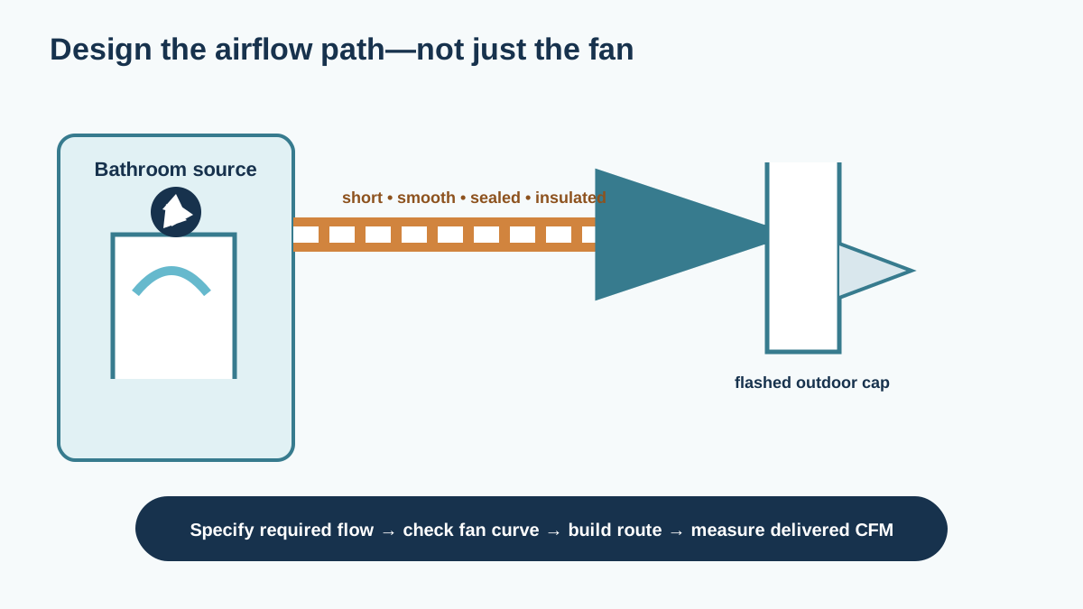
Short answer: Select a bath fan using the required local exhaust rate, room use, sound, controls, and its performance at the resistance of the actual duct system. Use the manufacturer-approved duct size, keep the run short and smooth, minimize bends, seal joints, insulate cold-space ducting, and terminate directly outdoors through a flashed cap with a working damper. Measure delivered airflow after installation; sound and a moving tissue do not prove adequate ventilation.
A fan can say “110 CFM” on the box and deliver far less through a crushed three-inch flex duct with four sharp bends and a stuck exterior flap. The room still fogs, the fan gets blamed, and a larger motor is connected to the same restrictive path.
Treat the project as four connected parts:
- required source-capture airflow;
- fan performance against duct resistance;
- a safe, condensation-managed outdoor route;
- controls and verification that make occupants actually use it.
First Diagnose the Existing System
Before shopping, observe a shower and trace the fan.
- Does the mirror remain fogged 20 minutes after use?
- Does moisture form on ceilings, windows, or exterior walls?
- Is paint peeling or caulk repeatedly growing mold?
- Does the grille collect heavy dust?
- Does the fan rattle, hum, or fail to start?
- Does the exterior damper open fully?
- Where does the duct terminate?
- Is the duct crushed, disconnected, wet, or uninsulated?
- Is the door undercut or transfer path adequate?
- Does the switch encourage the fan to run long enough?
A tissue held at the grille can show gross suction, not airflow. A fan can hold tissue while delivering a fraction of its target. Likewise, noise can come from turbulence and motor vibration rather than useful air movement.
Confirm outdoor termination
Every bath fan should discharge outdoors, not into an attic, soffit cavity, wall, garage, or crawlspace. “Near a roof vent” is not outdoors. Moist air released into a cold attic can create frost, wet insulation, mold, and roof-deck damage. Use the attic frost guide if the duct has leaked inside the enclosure.
Locate the exterior cap and check that it belongs to the fan. Operate one fan at a time. The damper should open and close without sticking, and the outlet should not be blocked by lint, paint, nests, snow, or a screen that the fan manufacturer prohibits.
How Much Airflow Does the Bathroom Need?
Local mechanical code and the adopted ventilation standard control the minimum. Requirements can distinguish intermittent and continuous operation and may account for floor area or fixture count. Do not treat an internet rule of thumb as code.
For project planning, document:
- bathroom floor area and ceiling height;
- shower, tub, jetted tub, toilet room, and door layout;
- whether one fan serves multiple pickup grilles;
- intermittent or continuous operation;
- required local exhaust rate;
- whether the fan contributes to whole-house ventilation;
- replacement-air path;
- climate and duct route.
A high ceiling increases room volume, but source capture near the shower often matters more than simply multiplying total cubic feet. A separate toilet compartment may need its own pickup. Large multi-fixture rooms may use multiple fans or a remote inline fan, provided the design prevents crossflow and meets code.
Why oversizing has limits
A larger fan may not overcome a small, rough duct. It can become louder, depressurize the bathroom, pull air from undesirable locations, or affect natural-draft combustion appliances elsewhere in the home. The correct system provides the needed airflow through a suitable duct with a predictable replacement-air path.
Read a Fan Performance Curve
Fan airflow falls as static pressure rises. The same model may deliver its headline airflow at one test pressure and much less through a restrictive installation. Look for a certified performance table showing CFM at several static pressures.
Resistance increases with:
- smaller duct diameter;
- longer total length;
- corrugated flexible duct;
- tight elbows immediately at the outlet;
- multiple elbows and reducers;
- crushed or sagging sections;
- restrictive caps and screens;
- backdraft dampers that do not open freely;
- dirty grilles and internal components.
PNNL guidance recommends smooth rigid duct, gradual bends, and - where possible - two to three feet of straight run before the first elbow. Follow the exact fan instructions. If the route demands high resistance, choose a fan designed to maintain flow at that pressure or redesign the route.
Equivalent length is a comparison tool
Designers often convert fittings into “equivalent feet” of straight duct. This is useful only when the fitting data and duct size match. One tight elbow can impose much more resistance than a long-radius elbow. Do not add generic numbers from unrelated products and call the result engineered.
Choose the Duct Route Before the Fan
Draw possible routes from the housing to a wall or roof cap. The best route is generally short, straight, serviceable, weatherproof, and compatible with structure and clearances.
Sidewall termination
A sidewall cap can allow a slightly downward route away from the fan, helping condensate move toward the exterior. It may avoid roof penetrations. Check clearances from windows, doors, air intakes, property lines, gas regulators, meters, grade, decks, and snow accumulation.
Roof termination
A roof cap can provide a direct path for top-floor bathrooms but must be flashed as part of the roofing system. Do not use a plumbing vent, ridge vent, or ordinary static attic vent. The cap needs a compatible damper and weather detail. Coordinate with a roofer, especially on low-slope, metal, tile, or warranted roofs.
Soffit termination
Some jurisdictions or designs restrict soffit discharge because moist exhaust can be drawn back into soffit intake vents or wet the eave. Use only an approved detail that controls re-entry and meets manufacturer and code requirements. Discharging loosely into the soffit cavity is not acceptable.
Lower-floor bathrooms
Joists, beams, plumbing, fire assemblies, and finished ceilings can complicate the path. Do not notch or drill structural framing without permitted design. An exterior-wall fan or remote inline fan may help, but sound, service access, cold-air leakage, fire stopping, and controls still need resolution.
Build the Duct Correctly
Use the diameter and materials allowed by the fan manufacturer and local code. Avoid reducing immediately from a larger fan outlet to an old small duct. Smooth rigid metal usually has lower resistance and is easier to support and seal than long flexible runs.
Key details:
- mechanically connect the duct to fan and cap as required;
- seal joints and longitudinal seams with compatible mastic or approved metal tape;
- do not use ordinary cloth-backed “duct tape” as a permanent air seal;
- orient and secure joints so condensate and airflow do not exploit open edges;
- support the duct to prevent sags;
- protect it from screws, storage, pests, and maintenance traffic;
- keep it separate from dryer, kitchen, plumbing, and combustion vents; a dryer needs its own model-specific route planned with the dryer vent length and routing guide;
- preserve firestopping at rated assemblies;
- provide access to service an inline fan.
Do not place screws where they create prohibited obstructions or puncture adjacent materials. Use the tested/listed connection method.
Prevent Duct Condensation
Warm humid exhaust can condense inside a cold duct. Cold outdoor air can also chill the housing or duct when the fan is off. Insulate ducting in unconditioned space to the required level and maintain a continuous exterior vapor-control jacket where the system calls for it.
Route the duct to manage any condensate rather than creating a low sag above the ceiling. PNNL notes that a sidewall termination slightly below the fan can allow the duct to slope away from the housing where feasible. Roof routes need their specified condensate and weather details.
If water drips from the grille:
- turn off power before opening electrical components;
- check for a duct sag or low point;
- verify insulation and exterior jacket continuity;
- confirm the cap damper closes;
- inspect whether snow or wind drives water into the cap;
- check joint leakage and duct slope;
- distinguish condensate from roof leakage;
- dry wet ceiling material promptly.
Air Seal and Insulate Around the Housing
The ceiling opening around a fan can be a large attic bypass. Air seal the fan housing to the ceiling air barrier using materials compatible with the housing, gap, temperature, and fire requirements. PNNL guidance describes inspecting and sealing this junction and using an insulation shield where needed.
Do not block required clearances, service panels, dampers, or cooling openings. Confirm whether the fan is rated for insulation contact. Restore full insulation coverage around and over the housing only as allowed.
A tight duct with a leaky ceiling cutout still sends indoor air into the attic. A sealed cutout with a disconnected duct still sends shower vapor there. Both details must pass.
Make Replacement Air Possible
An exhaust fan cannot move its rated air from a closed room unless air can enter. The replacement path is often a door undercut or transfer grille from the rest of the house. A thick rug, tight sweep, or closed solid door can restrict flow.
Test airflow with the bathroom door open and closed. If it falls significantly closed, improve the transfer path while preserving privacy, sound, light, and fire requirements. Do not simply pull replacement air from a garage, dirty crawlspace, or combustion zone.
Large exhaust systems can depressurize the home. Evaluate interactions with fireplaces and natural-draft appliances, especially when several fans and a range hood operate together. Working carbon-monoxide alarms are essential but do not replace combustion-safety testing.
Select Controls People Will Use
Countdown timer
A 10–60 minute countdown switch is intuitive for intermittent source control. The user can leave the room while the fan finishes drying. Choose a range suited to shower duration, climate, and measured clearance time.
Humidity-sensing control
This can respond when occupants forget the switch, but placement, calibration, baseline humidity, and seasonal conditions matter. It may run during humid outdoor weather or fail to react quickly if the sensor is isolated from the shower plume. Provide a manual override.
Occupancy control
Occupancy does not equal moisture. A toilet visit may not need a long run; a shower continues releasing moisture after the person leaves. Use occupancy as one input, not the only logic.
Continuous low speed with boost
Some fans support whole-house ventilation at low speed and local exhaust on boost. This requires a ventilation design, quiet certified operation, clear labeling, and commissioning. Do not convert an intermittent fan to continuous duty unless it is rated and the whole-house airflow is planned.
Smart controls
Connectivity is secondary to reliable local operation. The fan should still exhaust if Wi-Fi or an app fails. Avoid collecting unnecessary occupancy data for a basic moisture-control function.
Noise Is a Performance Feature
People turn off loud fans. Compare certified sone ratings at relevant operating points, but remember the installed duct and grille affect sound. Isolate vibration from framing, use the intended mounting hardware, and avoid turbulence at the outlet.
A quiet fan can be so unobtrusive that occupants forget it is on. A visible indicator, timer display, or well-labeled switch can help. For continuous ventilation, PNNL notes stringent sound expectations from ventilation standards; use the locally adopted requirement.
Measure Delivered Airflow
Commissioning is what separates a selected fan from a functioning system. Suitable methods include a calibrated flow hood, powered flow grid, or other accepted exhaust-flow measurement. A vane anemometer at one grille point is usually not enough because velocity is uneven.
Record:
- fan model and speed setting;
- measured flow with door open and closed;
- measurement instrument and date;
- exterior damper position;
- sound or vibration observations;
- control operation and run-on time;
- duct route, size, length, and fittings;
- whether other exhaust equipment was operating.
If airflow is low, inspect the grille, damper, duct size, bends, sags, joints, cap, and replacement-air path before installing a bigger fan.
Worked Comparison
Two quotes both specify a nominal 110-CFM fan.
Quote A reuses a long three-inch flexible duct with two crushed bends, ends at an attic vent, and includes no flow test. The fan's box rating is irrelevant to the unsafe termination and unknown resistance.
Quote B traces a short manufacturer-sized smooth duct to a flashed wall cap, seals and insulates the run, air seals the housing, adds a timer, and commits to a measured delivered flow. Quote B provides a verifiable ventilation system even if the fan itself costs the same.
Quote Scorecard
| Item | Strong proposal | Warning sign |
|---|---|---|
| Design airflow | Cites applicable requirement and use | “Biggest fan that fits” |
| Fan data | Performance at expected pressure | Box CFM only |
| Duct | Size, material, route, fittings, support | “Reuse existing” without inspection |
| Termination | Named outdoor cap, flashing, clearances | Attic or soffit cavity discharge |
| Condensation | Insulation, jacket, slope, damper | No cold-weather detail |
| Ceiling boundary | Housing air seal and insulation detail | Foam everything without clearance check |
| Controls | Timer/sensor/manual behavior | App-only control |
| Replacement air | Door/transfer path check | No closed-door test |
| Safety | Electrical, fire, combustion interaction | No permits or trade scope |
| Verification | Delivered-airflow measurement | Tissue test only |
Maintenance and Troubleshooting
Every few months or as the manufacturer requires, switch off power and clean the grille and accessible fan components. Check the exterior cap for debris, insects, ice, and damper operation. Inspect accessible attic ducting for separation, crushed insulation, water, or staining.
| Symptom | Likely checks |
|---|---|
| Fan loud, airflow low | Dirty grille, small duct, tight bend, stuck cap |
| Water drips from grille | Cold duct, sag, poor insulation, roof/cap entry |
| Mirror stays fogged | Low flow, short runtime, poor pickup, high house RH |
| Fan works only with door open | Restricted replacement-air path |
| Cold draft when off | Failed damper, wind exposure, leaky housing |
| Attic frost near fan | Duct leak/termination or ceiling bypass |
| Odor from another room | Shared duct or pressure/crossflow problem |
| Fan never stops | Sensor setting, high baseline RH, control fault |
A Practical Acceptance Test
Run this sequence with the installer before the ceiling is patched and again at final handoff.
- Photograph the full duct route, joints, insulation, and termination before concealment.
- Confirm the model, duct diameter, speed selection, and control settings match the submittal.
- Operate the fan and listen at the housing, first elbow, and exterior cap for vibration or obstruction.
- Confirm the exterior damper opens freely and does not chatter in normal wind.
- Measure airflow at the grille with the bathroom door open.
- Repeat with the door closed in its normal position.
- Operate other major exhaust equipment and document any material change or door pressure.
- Trigger the timer, humidity sensor, occupancy input, and manual override separately.
- Inspect the attic or chase for joint leakage with an accepted method.
- Confirm insulation covers the cold-space duct and approved housing areas continuously.
- Run a hot shower, then log room RH and surface clearance time.
- Reinspect after the first cold spell for condensate, frost, and cap icing.
Define failure before the test. If the delivered flow does not meet the project requirement, the installer should diagnose and correct the route, settings, cap, or replacement-air path. A promise that the motor “is rated for more” is not an acceptance result.
Fan Replacement Without Duct Replacement
Reusing an existing duct can reduce demolition, but inspect it end to end. Record its inside diameter, material, approximate length, elbows, reducers, support, insulation, joint condition, and outdoor cap. A new efficient fan connected to an undersized or damaged duct may deliver no better airflow.
Three outcomes are possible:
- Reuse as-is: only when the size, route, material, sealing, insulation, and cap suit the selected fan and measured flow passes.
- Repair and reuse: straighten or support sags, seal accessible joints, restore insulation, and replace a restrictive cap, then test.
- Replace or reroute: when diameter, hidden damage, termination, fire separation, condensate trapping, or access makes repair unreliable.
Do not assume the existing roof opening must be kept because it is convenient. Conversely, do not create a new roof penetration when an appropriate short wall route exists. Compare the full building detail and future service needs.
Remote Inline and Multi-Port Fans
An inline fan mounted away from the grille can reduce perceived bathroom noise and serve multiple pickup points. It also introduces balancing, branch resistance, backflow, access, vibration isolation, and control questions.
Each branch needs a designed flow. The shortest branch can steal air from the longest unless dampers or duct sizing balance them. The fan must remain accessible for cleaning and replacement; burying it above an inaccessible finished ceiling is not a maintenance plan. Condensate must not drain into the motor, and exterior discharge still needs the same flashing, clearances, and damper strategy.
For two bathrooms, confirm whether local code permits the arrangement and prevents one room's air from entering the other when the system is off. A dedicated fan per room is often simpler to verify.
Energy Use in Context
Fan electrical draw matters, especially for continuous operation, but heating or cooling replacement air can exceed the motor energy. That does not justify skipping ventilation. It means the home should use source capture effectively, avoid excessive runtime, and consider a designed balanced heat- or energy-recovery system when whole-house ventilation loads and climate justify it.
Compare products using certified airflow, sound, and efficacy at the relevant pressure. A low-watt fan that delivers inadequate air through the actual duct is not efficient in practice. A timer that clears moisture without running all day can improve both control and energy use for an intermittent-only system.
Frequently Asked Questions
Is 50, 80, or 110 CFM enough?
It depends on the applicable code, bathroom size and fixtures, intermittent or continuous operation, duct resistance, and delivered - not nominal - airflow.
Can a bathroom fan vent into the attic?
No. It should terminate directly outdoors through an appropriate cap. Attic discharge can wet insulation and roof sheathing.
Is flexible duct allowed?
Rules and fan instructions vary. Even where allowed, long, compressed, or sagging flex adds resistance and holds condensate. Smooth rigid duct generally performs more predictably.
Should the fan run during and after a shower?
Yes. Start it before or during the moisture event and continue until humidity and surfaces recover. ENERGY STAR consumer guidance commonly suggests about 20 minutes after showering; actual clearance can vary.
Does a humidity sensor replace the switch?
It should usually have a manual override. Sensors can miss a plume, drift, or run in humid weather.
Why does a new fan still seem weak?
The existing duct or cap may restrict it, or the closed bathroom may lack replacement air. Measure flow and inspect the system.
Can two bathrooms share one duct?
Only with a specifically designed system that prevents crossflow and meets code. Do not casually tee ordinary ceiling fans together.
Should I vent through the roof or wall?
Choose the shortest safe route with proper clearances, drainage, flashing, and serviceability. Either can work when detailed correctly.
Read Next
- Investigate roof-deck moisture with the attic frost guide.
- Diagnose room humidity using the window-condensation guide.
- Understand exhaust-driven pressure in the stack-effect guide.
- Include flow testing in a home energy audit.
Buy the fan last. First define the airflow, design the route, preserve the ceiling and weather barriers, and decide how success will be measured. Then select a fan that can perform in that system.
Sources and Verification
Sizing, ducting, exterior termination, air sealing, and commissioning guidance uses PNNL's bathroom-fan guide, PNNL exhaust-fan air-sealing guidance, and its existing-home ventilation guide. Moisture-control limits use the EPA mold and moisture guide. Product-specific airflow, duct size, controls, sound, clearances, electrical listing, local code, and measured field performance govern the installation.
What to Read Next
Attic Frost and Condensation 2026 Tool (Guide & Data)Use this next to compare the cost, incentive, installation, or operating-risk angle before you make a home energy decision.Sources and Verification
- PNNL Building America: Bathroom Exhaust Fans
- PNNL Building America: Air Sealing Bathroom and Kitchen Exhaust Fans
- PNNL Building America: WholeHouse Ventilation Strategies for Existing Homes
- PNNL Building America: Look at Exhaust Fans for Venting to Outside
- U.S. EPA: A Brief Guide to Mold, Moisture and Your Home
Editorial Review
EnergyBS Editorial Team
EnergyBS publishes practical homeowner guides. Important program, product, and cost claims should be checked against the linked source and local project documents before you commit to work.
Related Guides
View All ArticlesAttic Frost and Condensation 2026 Tool (Guide & Data)
Separate roof leaks from winter condensation, trace indoorair and exhaust paths, assess wet sheathing and insulation, and commission a safe attic repair.
Winter Window Condensation 2026 Guide & Data
Use condensation location, outdoor temperature, indoor humidity, surface temperature, and room conditions to separate normal coldsnap fogging from failed glass, leaks, and mold risk.
The Physics of Air Sealing: Why Your RValue Doesn't Matter (If You Don't Seal)
Insulation is just a sweater. Air sealing is the windbreaker. We explain the physics of the Stack Effect, why Rvalues lie, and how to stop your home from leaking energy like a sieve.