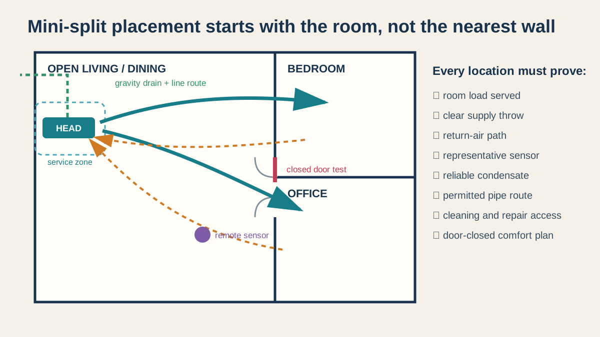
Ductless MiniSplit Head Placement: A RoombyRoom Planning Guide
A homeowner planning method for locating ductless indoor units by room load, air throw, doors, sensors, noise, condensate, line routes, service access, and wholehome comfort—not wall convenience alone.
The Short Answer
Short Answer: Place each ductless mini-split indoor unit only after mapping the room load, occupied zone, supply-air throw, return-air path, door-closed behavior, temperature sensor, condensate route, refrigerant-line route, noise exposure, and service access. A convenient exterior wall is not automatically the right wall. The best location sends conditioned air across the space without blowing directly on people, reads a representative room temperature, drains reliably, and remains accessible for cleaning and repair.
Whole-home ductless design is not “one head per floor” or “one head per bedroom” by rule. Open rooms can sometimes share air; closed rooms often cannot. A hallway may look central on a floor plan yet serve bedrooms poorly when doors close. This guide helps homeowners ask for a room-by-room placement plan before holes are drilled.
Final clearances, piping limits, mounting requirements, drain details, and permitted combinations always come from the exact manufacturer's instructions and local code. The planning method below organizes the decisions; it does not replace equipment-specific design.
The Placement Problem Has Seven Layers
Every proposed indoor-unit location must pass seven tests:
- Load: Is the unit selected for the rooms it is expected to serve?
- Throw: Can supply air travel through the occupied area without a nearby obstruction?
- Return: Can room air return freely to the unit's intake?
- Control: Will the built-in or remote sensor read a representative temperature?
- Water: Can condensate drain predictably and be cleaned?
- Route: Can piping, wiring, and the exterior penetration be built and protected well?
- Service: Can filters, coil, fan wheel, pump, electronics, and connections be reached later?
A location that passes only the first test is not complete. A head can have enough rated capacity and still create a cold sofa, warm bedroom, false thermostat reading, noisy pump, stained wall, or difficult repair.
Build a Room Load and Air-Path Map First
Start with a scaled floor plan. For every conditioned or indirectly served room, record:
- room-by-room heating and cooling load;
- ceiling height and large open volumes;
- exterior walls, windows, orientation, and major solar gain;
- doors and normal open/closed pattern;
- stairs and two-storey openings;
- occupancy and sleeping locations;
- heat-producing appliances or equipment;
- known hot, cold, humid, or drafty zones;
- planned insulation, air sealing, or window work;
- available indoor-unit types and mounting surfaces.
Manual J room loads are important because floor area does not describe exposure. A small west-facing office with computers and glass may have a higher cooling load than a larger interior bedroom. A corner bedroom over a garage may have a higher heating load than the central hall.
Draw arrows for intended supply-air travel and dotted arrows for return-air movement. Then draw doors closed. If the plan depends on air turning two corners, passing a closed door, moving through a narrow hall, or rising against buoyancy, mark that room as not reliably served until the designer proves otherwise.
One Head Per Zone Is a Design Result, Not a Rule
A zone is a space or group of spaces that can share one control and a plausible air path. It is not necessarily a floor, bedroom count, or outdoor-unit port.
Spaces that may share well
- an open kitchen, dining, and living area without tall partitions;
- a studio apartment;
- a primary bedroom with an open sitting area;
- connected rooms with wide, permanently open openings;
- a small well-insulated level with an intentionally designed transfer-air path.
Spaces that often need separate analysis
- bedrooms with doors closed overnight;
- a home office with strong solar or equipment gains;
- a room over a garage;
- finished attic or basement rooms separated by stairs and doors;
- bathrooms that need warmth but have no practical indoor-unit location;
- rooms at opposite ends of a long corridor;
- high-ceiling rooms beside normal-height rooms;
- additions with different envelope quality.
Do not solve a distribution problem simply by adding heads. Multi-zone outdoor units have permitted indoor-unit combinations, connected-capacity rules, diversity behavior, minimum output, and limits on simultaneous delivery. A room with a tiny load can be uncomfortable if its smallest available head is oversized. A compact ducted unit serving several bedrooms may be better than multiple wall heads; in another house, separate single-zone systems may provide better turndown and redundancy.
Ask the designer to show the load assigned to each indoor unit and the exact indoor/outdoor combination's capacity at relevant conditions.
Choose the Indoor-Unit Type Before the Exact Location
High-wall unit
High-wall heads are common because they can create a long horizontal throw, keep floor area clear, and often allow a short route through an exterior wall. They need adequate space above and beside the cabinet under the exact installation manual. The wall must support the mounting plate, remain flat, and allow the unit to be removed or opened.
High-wall units work best when they face the long dimension of an open room. They are weaker choices when the only wall points directly at a bed or sofa, is blocked by a tall cabinet, traps air in an alcove, or places the return near a heat source.
Floor-mounted console
A floor console can fit beneath windows or sloped ceilings and may feel familiar in heating-dominated rooms. It occupies wall and furniture space, sits closer to dust and impacts, and needs clear supply and return paths. Curtains and furniture layouts must be considered before selection.
Ceiling cassette
A cassette can distribute air in several directions and reduce visible wall equipment. It needs adequate ceiling cavity, structural support, service access, a condensate solution, and a finish plan. A cassette is not invisible maintenance: filters, drain pans, pumps, and connections still require access.
Compact concealed ducted unit
A short-duct air handler can serve a cluster such as bedrooms while keeping equipment out of each room. It introduces duct design, static pressure, insulation, sealing, balancing, return-air, and access requirements. Small ducts are not exempt from distribution design.
Specialty or mixed systems
Some projects combine wall, floor, cassette, and ducted units. Verify that every indoor unit is an approved match for the outdoor unit and that combined connected capacity and piping remain within manufacturer limits.
Supply-Air Throw: Aim Through the Room, Not at a Person
The indoor unit should generally send air into the longest unobstructed path across the served zone. “Generally” matters because the exact unit's louver patterns, ceiling height, capacity, furnishings, and operating mode change the result.
For each candidate wall, sketch:
- initial supply direction in cooling;
- likely supply direction in heating;
- nearest wall, beam, cabinet, curtain, or pendant light;
- occupied seating, desk, dining, and sleeping zones;
- areas hidden around corners or behind partitions;
- expected louver sweep.
Avoid positioning the head so normal operation blows directly onto a bed, desk chair, sofa, crib, or dining seat. A room can meet average temperature while an occupant remains uncomfortable in the high-velocity or cool-air stream.
Do not place a high-wall head immediately above a tall bookcase or wardrobe that blocks discharge. Avoid narrow wall pockets where the jet strikes the opposite wall almost immediately and short-circuits back to the return.
Heating and cooling air do not behave identically
Cool supply air tends to sink; warm supply air tends to rise. Louvers and fan speed help distribute both modes, but a location that looks adequate for summer can leave floor-level winter discomfort in a high room, while a floor console chosen for heating may distribute cooling differently. Ask the installer to discuss both seasonal patterns.
Ceiling fans can help mix large or high spaces, but they should not be used to rescue a fundamentally obstructed location. Record expected fan direction and speed in the operating plan.
Return Air and Short-Circuiting
The intake needs a broad, unobstructed sample of room air. The unit should not pull most of its return directly from its own supply stream. This “short circuit” can satisfy the sensor while the far side of the room remains uncomfortable.
Risk increases when:
- the unit is squeezed into a shallow alcove;
- discharge strikes a nearby wall and rebounds;
- a beam or soffit separates the head from the room;
- a tall cabinet sits below the head;
- curtains are drawn across the intake;
- the unit faces a stair opening instead of the occupied level;
- furniture creates a local recirculation pocket.
Photograph each candidate wall with furniture shown. A blank construction drawing is not enough if a future wardrobe occupies the only return path.
Doors, Hallways, and Bedrooms
An open door can transfer some conditioned air. It does not guarantee that a closed bedroom follows the hall temperature overnight.
Use a door-state schedule:
| Room | Door by day | Door at night | Dedicated unit? | Designed transfer path? | Residual load plan |
|---|---|---|---|---|---|
| Primary bedroom | Open | Closed | |||
| Bedroom 2 | Open | Closed | |||
| Office | Closed | Open | |||
| Bathroom | Closed intermittently | Closed |
Transfer grilles, jump ducts, undercuts, or small distribution fans may help in some designs, but each has airflow, privacy, noise, fire/smoke, and code implications. Do not assume a door undercut carries a significant room load without design evidence.
A hallway head often underperforms because halls have low direct load while the rooms behind closed doors have the real load. The hall sensor becomes satisfied first. Put equipment where the load and occupants are, or provide an engineered way for air to reach them.
Stairs, Open Levels, and Stack Effect
Stairwells are tempting “central” locations. They are also strong air pathways that change seasonally.
In heating mode, warm air delivered near a stair may rise to the upper level rather than serve the lower occupied zone. In cooling mode, cool air may descend, but solar gains and closed rooms can still defeat the assumption. Building air leakage and stack effect add another layer during cold weather.
For an open two-storey plan, require separate load and airflow reasoning for each level. Consider:
- where supply air travels in both modes;
- where return air comes from;
- temperature stratification at the sensor;
- upper-level solar gains;
- bedroom doors;
- ceiling fans or other mixing;
- whether separate zones improve control.
Do not accept “heat rises” as a complete design. Heat moves in multiple ways, and the equipment must both deliver and sense conditions in the intended zones.
Sensor Placement and Temperature Bias
Many wall heads control from a sensor in the indoor unit. That sensor may see a different temperature from the occupied zone because it is high on the wall, near a ceiling pocket, close to the supply-return loop, or affected by an exterior wall.
Potential bias sources include:
- direct sun on the cabinet;
- kitchen cooking heat;
- electronics or lighting;
- fireplace or wood stove;
- exterior-door drafts;
- stratification in a tall room;
- a head mounted in a hall while serving bedrooms;
- warm piping chase or cold exterior-wall cavity;
- supply air returning too quickly.
Ask whether the system supports a wired or wireless remote room sensor, which sensor becomes primary, and how control changes during a communication failure. A handheld remote may contain no room sensor, or its sensor may not control in every mode; verify the exact model.
For a remote sensor, choose a representative occupied location away from sun, drafts, supply air, appliances, and unusual wall temperatures. Document its location on the final plan so it is not moved like an ordinary remote control.
Condensate: Let the Water Plan Shape the Location
Cooling and dehumidification create condensate. The drain must move that water to an approved termination without hidden sags, reverse slope, freeze exposure, staining, pests, or inaccessible maintenance points.
Gravity drainage
Gravity is usually simpler when the exact unit and route permit it. The installer still must follow required slope, risk, vent, diameter, support, insulation, termination, and test procedures. A long horizontal route inside a wall can be difficult to verify and clean.
Condensate pump
A pump can open placement options, but it adds noise, power, tubing, cleaning, and a failure mode. Record:
- pump model and location;
- sound exposure in bedrooms or offices;
- access for service and replacement;
- alarm or shutdown behavior;
- tubing route and termination;
- check-valve and lift limitations under its instructions;
- who maintains it and how often it is inspected.
Do not hide a pump where the only access requires removing finished cabinetry or opening a ceiling. If a gravity route is available from a slightly different wall, compare the comfort benefit of the preferred location with the pump's lifetime burden.
The mini-split gravity-versus-pump guide provides the pre-install route, shutdown, termination, and water-test worksheet. The AC condensate drain guide explains symptoms and maintenance boundaries for existing water problems.
Refrigerant Line, Wiring, and Wall Penetration
Indoor-unit placement determines the line-set route. A short direct route can reduce finishes and joints, but the shortest route is not always the best comfort location.
For each option, draw:
- liquid and vapor piping route;
- control/power wiring route;
- condensate route;
- interior and exterior line-hide route;
- wall, rim-joist, roof, or foundation penetration;
- fire, weather, pest, and air-sealing detail;
- bends, elevation change, and approximate equivalent length;
- service connection location;
- future access.
Avoid unexamined hidden joints. Protect exterior line insulation from weather, ultraviolet exposure, pests, and physical damage using approved materials. Seal the building penetration for water, air, and pests without trapping drain water.
Manufacturer piping tables establish allowable diameters, lengths, elevation differences, additional charge, and installation procedures. A route that fits visually may be outside those limits. The exact design should be checked before the wall plate is mounted.
Wall Structure, Finishes, and Mounting
The mounting surface must be strong, flat, and suitable for the specified anchors and plate. Locate studs, utilities, masonry conditions, and concealed obstacles before drilling. Discuss:
- plaster, tile, concrete, brick, or fragile finishes;
- electrical, plumbing, and structural conflicts;
- vibration isolation under the instructions;
- wall staining or ghosting risk;
- visible line hide and exterior appearance;
- removal path for future replacement;
- patching responsibility.
Never compromise structural or fire assemblies casually for a shorter line route. Penetrations through rated separations, garages, shared walls, or roofs require the applicable permitted detail.
Clearances and Service Access
Do not copy a generic clearance from the internet. Use the installation and service instructions for the exact indoor unit. Building Science Education guidance emphasizes maintaining manufacturer-required top clearance for ductless units.
Test access with real tasks:
- Can the front panel open fully?
- Can filters slide out without hitting the ceiling or furniture?
- Can a technician remove the fan wheel or drain pan?
- Can electrical covers and flare or piping connections be reached?
- Can a cleaning bib be installed without damaging the wall?
- Can a cassette filter and pump be accessed?
- Can a concealed unit be replaced through the access opening?
A unit may meet installation clearance yet be miserable to deep-clean. Ask the installer to demonstrate the service path on the plan.
Noise and Vibration Planning
Indoor sound ratings are useful, but placement controls how noise is experienced. A quiet head can still disturb sleep if fan changes, louvers, refrigerant flow, expansion sounds, or a condensate pump occur directly above the bed.
Map sensitive locations:
- bed headboards;
- work calls and recording areas;
- television and listening positions;
- nursery or light sleeper rooms;
- shared walls with neighbors;
- closets or framing that may transmit vibration.
Ask how low-temperature heating, defrost, and multi-zone operation affect sound. The outdoor unit also needs a separate acoustic review; do not place it under a bedroom window or beside a neighbor's quiet area merely to shorten piping.
Outdoor Unit Placement Is Part of the Indoor Plan
Every indoor route converges at an outdoor unit. Evaluate:
- manufacturer air and service clearances;
- snow depth, drifting, roof slide, and meltwater;
- defrost drainage and refreezing;
- flood and roof-runoff exposure;
- vegetation and debris;
- sound and vibration;
- protection from vehicle, mower, and foot traffic;
- line-set length and elevation;
- disconnect and service access;
- appearance and local setback rules.
Do not enclose the outdoor unit with a decorative screen that restricts airflow or service. In snow climates, elevation and drainage need a site-specific plan; a universal stand height is not appropriate.
A Four-Candidate Wall Comparison
For each room, score up to four locations from 0 to 2: 0 fails, 1 workable with mitigation, 2 strong.
| Criterion | Wall A | Wall B | Wall C | Wall D |
|---|---|---|---|---|
| Serves documented room load | ||||
| Long, unobstructed throw | ||||
| Avoids direct occupant draft | ||||
| Representative sensor condition | ||||
| Gravity condensate route | ||||
| Acceptable piping route | ||||
| Manufacturer clearances | ||||
| Filter and deep-service access | ||||
| Low noise exposure | ||||
| Good exterior finish |
Treat load, manufacturer clearance, permitted piping, safe mounting, and water management as gates rather than points. A high total cannot rescue a failed gate.
Worked Example: Two Bedrooms and an Open Main Floor
Consider a hypothetical compact two-storey home:
- open living/dining/kitchen main floor: 15,000 Btu/h design heating load;
- primary bedroom: 5,500 Btu/h;
- second bedroom/office: 4,500 Btu/h;
- upstairs hall and bath: 2,500 Btu/h combined;
- bedroom doors close at night;
- only the rear wall offers an easy exterior route.
The first proposal places one large head over the main-floor rear door and one head in the upstairs hall. It is inexpensive and requires two penetrations. The plan fails to explain closed-bedroom delivery. The hall has little direct load, so its sensor may satisfy while bedrooms remain cold or warm.
A second concept places a correctly selected main-floor head facing the long open dimension and uses a small concealed ducted unit for the bedroom cluster. Short branches are sized for room loads, with a central return and accessible service panel. This costs more and introduces duct/static design, but it serves closed rooms deliberately.
A third concept gives each bedroom a small wall head. It offers individual control but may oversize the small room, increase maintenance points, and force a multi-zone combination with a higher minimum outdoor-unit output. Separate single-zone systems may perform differently. The designer must compare exact combination data rather than assuming more heads equal better comfort.
There is no automatic winner. The useful comparison is:
room loads + door behavior + minimum equipment output + airflow path + lifetime service burden + installed cost.
Common Placement Failures and Better Questions
“Put it above the door because the lines go straight outside”
Ask where supply air travels, whether the open door blocks or redirects it, how the sensor reads, and whether a slightly longer approved route improves the occupied-zone result.
“One head in the hall will do the whole floor”
Ask for the door-closed room loads and designed transfer path. If no path exists, request a different indoor-unit or distribution concept.
“The remote fixes the thermostat problem”
Ask whether the exact remote actually contains the controlling sensor, in which modes, and where it will remain permanently.
“A pump lets us place it anywhere”
Ask about sound, access, alarm/shutdown, tubing, maintenance, replacement, and water-damage consequences.
“The unit is small, so clearance is fine”
Ask to see the exact installation and service clearances and demonstrate filter, coil, fan, drain, and electronics access.
“The multi-zone condenser handles any combination”
Ask for the manufacturer's approved combination, connected capacity, piping table, and capacity available to each zone at design conditions.
Pre-Installation Walkthrough Checklist
- Exact indoor and outdoor model numbers are on the plan.
- Room-by-room heating and cooling loads are available.
- Each room is marked directly served, indirectly served, or intentionally unconditioned.
- Door-closed sleeping and working conditions are addressed.
- Supply and return-air arrows are drawn for both modes.
- Beds, desks, sofas, tall furniture, curtains, and cabinets are shown.
- Sensor location and control logic are documented.
- Condensate route, slope or pump, termination, and service are documented.
- Piping, wiring, penetration, exterior cover, and finish are agreed.
- Manufacturer clearances and piping limits are checked.
- Filter and deep-service tasks can be performed.
- Indoor and outdoor noise-sensitive locations are reviewed.
- Outdoor snow, drainage, debris, and service conditions are addressed.
- Wall repair, painting, line hide, and cleanup responsibilities are written.
- Photos of final routes and hidden work will be added to the owner file.
Mark the wall plate and line-hide route with removable tape before installation. Stand at beds, chairs, workstations, and doorways. Open cabinets and curtains. If the plan feels awkward before drilling, it will not improve after the lines are connected.
Commission the Placement, Not Just the Machine
After startup, test how the installed location works:
- operate heating and cooling when weather permits;
- confirm louvers move through intended directions;
- measure or log occupied-zone temperature separately from the head reading;
- close bedroom doors under the normal schedule;
- listen for fan, louver, refrigerant, pump, and vibration noise;
- test condensate drainage and safety behavior;
- verify remote-sensor selection;
- confirm filters and access panels can be removed;
- record control settings and owner instructions.
Some comfort patterns appear only over several days or at seasonal extremes. Agree on a callback process and define which observations the homeowner should log: outdoor temperature, setpoint, head reading, independent room reading, door state, fan setting, and time.
Do not respond to every problem by increasing setpoint or fan speed. A persistent room difference may indicate load, placement, distribution, sensor, or envelope issues.
Sources and Verification
This placement method uses primary technical guidance rather than generic room-count rules:
- DOE Building Science Education's Guide to Installing Air-Source Heat Pumps covers load calculation, equipment selection, location, condensate, piping, and commissioning considerations.
- PNNL's ductless mini-split resource guide describes ductless system configuration and retrofit considerations.
- PNNL's cold-climate sizing and selection guide supports matching performance to local loads and temperatures rather than relying on nominal capacity.
- ACCA Manual J is the industry load-calculation basis used for room-by-room heating and cooling needs.
Clearances, piping limits, condensate requirements, approved combinations, and service access are product-specific. Verify the current installation manual for every indoor and outdoor model before drilling or ordering equipment.
Frequently Asked Questions
How high should a mini-split head be mounted?
Use the exact manufacturer's minimum and maximum clearances, mounting instructions, and service requirements. “Near the ceiling” is not a complete dimension. DOE's installation guide supports treating location and installation details as part of system performance; the exact product manual supplies the dimensions.
Can a mini-split head go above a window?
Sometimes, if structure, clearances, curtains, sensor conditions, throw, piping, drainage, and service access all work. Window headers, trim, direct sun, and curtain interference can make the location unsuitable.
Is it okay to put a mini-split above a bed?
It can be physically possible but is often poor for draft and noise exposure. Compare an adjacent wall that throws air across rather than directly onto the bed. If no alternative exists, review louver control, low fan behavior, sensor location, and service access before committing.
Can one head heat several bedrooms?
Only if a designed air path and room-load analysis support it under real door conditions. ACCA Manual J provides the load-calculation basis, while PNNL's ductless-system guidance provides system context. Do not rely on hallway temperature alone.
Does every indoor unit need a drain?
Indoor units that cool or dehumidify need a condensate-management path. The form varies by unit type. DOE's air-source heat-pump installation guide includes condensate and installation considerations; the exact manual controls routing and limits.
Are more indoor heads always better?
No. More heads add control but also cost, cleaning, piping, wall impact, and possible oversizing. The best count follows room loads, doors, equipment minimum capacity, approved combinations, and homeowner use.
Can I move furniture after installation?
Yes, but tall furniture, curtains, shelving, and room dividers can obstruct supply, return, sensors, or service access. Preserve the mapped air path and required clearances.
What to Read Next
Use the Manual J heat-pump sizing guide to define each room's load, then put the placement and commissioning scope into the heat-pump quote comparison worksheet. Plan water with the mini-split condensate route guide. If the proposed route retains existing refrigerant piping, review the line-set reuse-versus-replacement decision guide before accepting “reuse” as a generic allowance.
Sources and Verification
Editorial Review
EnergyBS Editorial Team
EnergyBS publishes practical homeowner guides. Important program, product, and cost claims should be checked against the linked source and local project documents before you commit to work.
Related Guides
View All ArticlesHeat Pump Sizing Guide: How to Read a Manual J and Avoid an Oversized System
A homeownerfocused guide to Manual J loads, Manual S equipment selection, coldweather capacity, balance points, duct constraints, and the documents a defensible heatpump quote should include.
Cold Climate Heat Pump Performance Data: RealWorld Efficiency and Costs
Can heat pumps handle subzero winters? We audit realworld performance data, Coefficient of Performance (COP) curves in extreme cold, and actual utility bill impacts.
Heat Pump Quote Comparison Worksheet: Normalize Price, Design, and Commissioning
A sidebyside homeowner worksheet for comparing heatpump and HVAC bids by load calculations, exact matched equipment, ducts, electrical work, refrigerant piping, controls, commissioning, warranties, exclusions, and true installed cost.