Frozen AC Evaporator Coil: Thaw It Safely, Then Prove Why It Froze
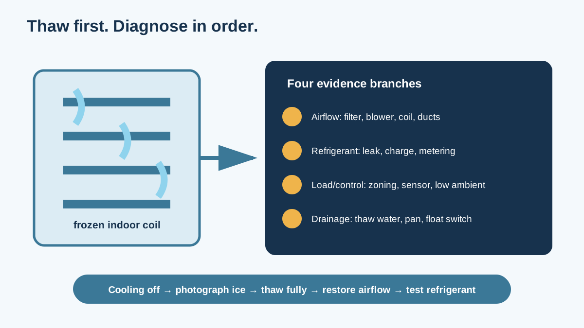
Stop compressor operation, manage thaw water, document airflow and ice patterns, and separate filter, blower, duct, coil, thermostat, and refrigerant causes before authorizing repairs.
Direct Answer
Stop compressor operation, manage thaw water, document airflow and ice patterns, and separate filter, blower, duct, coil, thermostat, and refrigerant causes before authorizing repairs.
Quick Checks
- 1Turn cooling off; continuing to run the compressor against a frozen coil can worsen damage.
- 2Do not chip ice, apply a heat gun, or pour hot water into the air handler.
- 3Require airflow and refrigerant-circuit evidence before approving a refrigerant recharge.
Ice Means the Coil Stayed Below Freezing
Short answer: Turn cooling off when the indoor coil or large refrigerant line is iced. Follow the equipment instructions; fan-only operation may speed thawing if the blower works and water can drain safely. A frozen coil usually points to inadequate airflow, abnormal refrigerant pressure/feeding, low load, or a control/blower fault. Let it thaw fully before testing. Never chip the ice or keep lowering the thermostat.
Ice blocks airflow, hides the original pattern, and can send thaw water outside the drain pan. The first job is to protect the equipment and building. The second is to collect evidence before someone adds refrigerant by habit.
Stop and Protect the Area
- Set the thermostat to cooling off.
- Follow the air-handler and thermostat instructions.
- Use fan-only only if the blower operates normally and the manual allows it.
- Check the floor, ceiling, drain pan, and nearby electrical area for water.
- Move belongings out of the possible drip path.
- Do not open energized equipment or remove ice mechanically.
- Call service for electrical odor, arcing, a failed blower, repeated breaker trips, or water near live components.
Never use a torch, heat gun, hair dryer, sharp tool, or boiling water. Coil fins and refrigerant tubes are thin. Puncturing a tube can release refrigerant and turn a diagnostic call into a major repair.
EPA rules prohibit intentional venting of many refrigerants. Refrigerant recovery, leak work, and charging require appropriate equipment and qualified personnel.
Photograph the Ice Before It Melts
From safe accessible locations, photograph:
- the exposed large insulated suction line near the indoor unit;
- any visible distributor tubes or coil face;
- filter condition and model;
- thermostat mode, set point, and room temperature;
- water in primary or auxiliary pans;
- outdoor-unit condition;
- frost location along refrigerant piping;
- return and supply grille blockage;
- fault codes or alerts.
The pattern matters. An evenly iced coil can fit a broad airflow problem. Ice limited to one coil circuit or the first part of the coil may point toward refrigerant distribution, charge, or a local airflow defect. Pattern alone doesn't prove the cause, but thawing erases it.
Build a Timeline
| Time/event | Thermostat | Indoor airflow | Ice/water | Outdoor unit |
|---|---|---|---|---|
| 2 p.m. | 74°F set, 78°F room | Normal | None seen | Running |
| 5 p.m. | 72°F set, 80°F room | Weak | Frost on large line | Running continuously |
| 7 p.m. | Cooling off | Fan weak | Heavy cabinet ice | Off |
| 10 p.m. | Fan only | Improving | Pan draining | Off |
| Next morning | Off | — | Fully thawed | — |
Note filter age, doors/registers, outdoor temperature, humidity, cooking or shower loads, and whether the problem followed service, construction dust, a new filter, duct work, or thermostat replacement.
Why a Coil Freezes
Refrigerant boils inside the evaporator by absorbing heat from indoor air. Under normal cooling conditions, the coil is cold enough to condense water but warm enough to stay above freezing. Ice forms when some part of the surface falls below 32°F while moisture is available.
That can happen when:
- too little warm air crosses the coil;
- refrigerant pressure/temperature is abnormally low;
- refrigerant distribution starves part of the coil;
- the blower stops or runs at the wrong speed;
- cooling continues under a very low indoor load;
- a thermostat or sensor keeps the compressor on incorrectly;
- a dirty or damaged coil creates uneven heat transfer.
The visible ice is downstream of the fault.
Airflow Causes Come First
Dirty or restrictive filter
Turn equipment off as directed and inspect the filter. Confirm size, orientation, loading, and whether more than one filter is installed. Replace or clean it only with the correct type.
A high-MERV filter isn't automatically restrictive; face area, depth, media design, airflow, and dirt load determine pressure drop. The MERV airflow guide shows how to compare measured pressure rather than ratings alone.
Blocked returns and closed supplies
Furniture, rugs, storage, and closed dampers can reduce system flow. Open registers meant to be open. Do not close rooms to “save cooling” without understanding return paths and duct pressure.
Blower faults
A failed capacitor, motor, control module, relay, wheel, belt, or speed configuration can reduce or stop airflow. Dirt on the blower wheel lowers performance. These checks involve moving parts and electrical hazards and belong to a technician.
Dirty evaporator coil
DOE's air-conditioner diagnostic guidance notes that coil fouling reduces airflow and can eventually cause freeze-up. Construction dust and filter bypass can mat the entering face, which may be hidden from the access panel.
Cleaning method must protect fins, coatings, electronics, drain pan, occupied air, and wastewater route. Do not spray an unknown cleaner into the cabinet.
Duct restriction or leakage
Collapsed flex duct, a blocked coil, closed fire/smoke damper, undersized return, or major leakage can reduce delivered and coil airflow. Measure total external static pressure and component pressure drops. The duct diagnostic guide provides a commissioning table.
Refrigerant-Side Causes Need Measurements
Low refrigerant charge is commonly caused by a leak, not normal consumption. Refrigerant does not get “used up” like fuel. Adding charge without locating and evaluating a leak can produce a short-lived repair and more emissions.
A qualified technician may measure:
- suction and liquid pressures;
- line temperatures;
- superheat and subcooling using the system's charging method;
- indoor/outdoor temperature and humidity;
- airflow or an accepted proxy;
- coil temperature distribution;
- metering-device behavior;
- refrigerant type and equipment charge specification;
- leak-test results.
Charge diagnostics without verified airflow can mislead. Low airflow changes pressures and temperatures. Thaw the coil, restore airflow, then test at conditions allowed by the manufacturer.
Leak evidence
Oil residue can suggest a leak but isn't conclusive. Electronic detection, bubble solution, pressure testing, isolation, or other methods may be needed. Ask the contractor to state where the leak was found, how it was confirmed, whether repair is practical, and how the final charge was weighed or verified.
Metering and restriction faults
A restricted filter-drier, kinked tube, blocked distributor, or faulty expansion device can starve part of the evaporator. The ice pattern and circuit temperatures can help, but internal refrigerant work is not a homeowner task.
Low Load and Control Problems
Air conditioners need enough indoor heat load and airflow. Running cooling in very cool outdoor weather, setting the thermostat unusually low, or cooling a small zone with a large system can drive coil temperature down.
Special low-ambient controls may be required for server rooms or other year-round cooling. A normal residential thermostat setting is not a substitute for that design.
Check whether:
- the thermostat is near a supply register or cold surface;
- a remote sensor reads the wrong room;
- zoning leaves too little duct area open;
- fan speed was changed during service;
- the compressor runs when the blower doesn't;
- a contactor or control sticks;
- dehumidification mode intentionally lowers airflow beyond safe limits;
- a smart control is configured for the wrong equipment.
Do not jumper controls or force compressor operation for testing.
Thawing and Water Management
A heavily iced coil can release many gallons as it melts. Confirm the primary drain and any condensate pump can handle the flow. Watch auxiliary pans and ceilings below attic equipment.
If water rises, a float switch may stop the system. Do not bypass it. The separate condensate overflow guide explains traps, pans, switches, and drain diagnosis.
Do not restart cooling until the coil is fully thawed. Ice inside the coil block may remain after the visible line clears. A technician needs access to verify the coil and drain pan.
The Post-Thaw Diagnostic Order
- Confirm filter and all intended airflow paths.
- Inspect blower operation and coil cleanliness.
- Inspect drain pan, risk, drain, and float switches.
- Measure total external static and component pressure drops.
- Set blower airflow according to equipment and humidity needs.
- Run the system at valid indoor/outdoor test conditions.
- Measure refrigerant circuit using the manufacturer's procedure.
- Check controls, sensors, staging, and zoning.
- Observe coil temperature distribution and condensate formation.
- Document a stable run after repair.
This order prevents adding refrigerant to a dirty-filter or failed-blower problem.
A Sensible Service Report
| Evidence | Before | Required/reference | After |
|---|---|---|---|
| Filter model/condition | Equipment allowance | ||
| Total external static | Blower table | ||
| Filter pressure drop | Design budget | ||
| Coil pressure drop | Manufacturer/diagnostic | ||
| Blower setting/airflow | Matched system need | ||
| Return DB/WB or RH | Test condition | ||
| Supply temperature | Expected operation | ||
| Suction/liquid pressure | Refrigerant procedure | ||
| Superheat/subcooling | Charging target | ||
| Refrigerant added/recovered | Weight and reason | ||
| Leak location/method | Repair evidence | ||
| Stable runtime | No new frost |
DB means dry-bulb temperature; WB means wet-bulb. The contractor should explain the readings in plain language.
A Worked Airflow Example
Suppose a nominal three-ton cooling system is configured around 400 CFM per ton. The rough target would be 1,200 CFM, but the exact design can differ for climate, latent load, equipment, and manufacturer limits.
If measured airflow is only 750 CFM, adding refrigerant is not the first step. The technician should find the restriction or blower setup, restore valid airflow, and then repeat refrigerant diagnostics. This example shows order of operations, not a universal 400-CFM rule.
Repair, Leak Repair, or Replacement?
Repair can make sense for a filter, blower component, duct restriction, dirty coil, control, accessible leak, or metering component when the rest of the system is sound.
Replacement moves higher when the coil is badly corroded, a refrigerant phaseout or availability issue makes repair impractical, the compressor is damaged, matched-system compatibility is poor, or repair cost approaches a properly designed new system. Ask for:
- confirmed cause;
- repair scope and warranty;
- refrigerant and matched equipment details;
- load calculation if capacity changes;
- duct/static-pressure corrections;
- commissioning values;
- disposal and refrigerant recovery method.
Measure Static Pressure by Component
Total external static pressure tells you how hard the blower works against the installed system. It doesn't locate the restriction. Measure pressure drops across the filter, indoor coil, supply system, and return system at the operating airflow.
| Component | Pressure before | Pressure after | Drop | Interpretation question |
|---|---|---|---|---|
| Filter | Is media loaded or area too small? | |||
| Evaporator coil | Is the entering face fouled or wet? | |||
| Return duct | Is grille/duct area restrictive? | |||
| Supply duct | Are dampers, flex, or outlets restrictive? | |||
| Whole external system | Is blower within its allowed range? |
Pressure taps must be placed safely and interpreted using the exact air-handler or furnace blower table. A high reading across a wet coil may change after the coil dries. A low total reading doesn't prove good airflow if the blower is set too slowly.
Ask the technician to leave the tap locations sealed after testing.
Variable-Speed and Dehumidification Settings
Variable-speed equipment may intentionally lower airflow to remove more moisture. That can improve comfort, but only within the matched system's allowed range. Wrong dip-switch, thermostat, communicating-control, or dehumidification settings can drive coil temperature too low.
Document:
- cooling tonnage selected in controls;
- nominal airflow and dehumidification reduction;
- blower delay/profile;
- zoning minimum airflow;
- continuous fan setting;
- thermostat humidity target;
- outdoor-unit stage during the event;
- indoor coil and outdoor unit match.
If freezing began after a board, thermostat, motor, or outdoor unit replacement, compare configuration with the pre-service record. “Factory default” may not match the installed coil and ducts.
Why Continuous Fan Can Change Humidity
After the compressor stops, water remains on the evaporator. Continuous fan operation can re-evaporate some moisture into the house instead of letting it drain, depending on the system and climate. Fan-only is useful for thawing under supervision, but it isn't automatically the best permanent cooling-season setting.
Use the thermostat and equipment guidance. After repair, compare indoor RH and condensate behavior with auto fan versus any proposed continuous setting. Do not solve icing by leaving the blower on forever without fixing the cause.
Attic and Crawlspace Air Handlers
A frozen coil in an attic or crawlspace creates extra building risk. Thaw water can overflow into ceilings or wet framing. A hot, humid attic can also condense on cold cabinets and ducts, making it hard to tell drain overflow from exterior sweating.
Inspect:
- auxiliary pan size and corrosion;
- float switches and shutdown wiring;
- primary and secondary drain outlets;
- risk and vent arrangement;
- cabinet and suction-line insulation;
- condensate-pump power and discharge;
- ceiling stains beneath the full unit and drain route;
- service platform and safe access;
- air leakage at cabinet panels and duct connections.
Do not climb into an unsafe attic to monitor a thaw. Shut cooling off and use qualified service when water can damage ceilings or electrical systems.
Mini-Split and Ductless Freeze Patterns
Ductless indoor heads can freeze because of dirty washable filters, a fouled coil or blower wheel, blocked airflow, control/sensor faults, refrigerant issues, or installation defects. The homeowner-accessible maintenance differs from a central air handler.
Follow the exact model's filter-cleaning steps. Do not bend louvers, spray electronics, or dismantle the blower. Photograph which head froze and whether other heads on the same outdoor unit operated normally.
Multi-zone systems add refrigerant distribution and control interactions. A problem in one head doesn't prove the shared outdoor charge is low. The technician should inspect the affected circuit, sensors, electronic expansion control, line length/configuration, and other zones.
Heat-Pump Cooling Versus Heating Ice
This guide addresses ice at the indoor evaporator during cooling. Frost on an outdoor heat-pump coil during winter heating can be normal before a defrost cycle. The two conditions use different diagnostic paths.
In cooling mode:
- the indoor coil is the evaporator;
- indoor ice is abnormal;
- indoor airflow and refrigerant diagnostics matter;
- thaw water enters the indoor drain system.
In heating mode:
- the outdoor coil is the evaporator;
- frost can be expected under some weather;
- defrost controls and outdoor drainage matter;
- thick persistent ice still needs service.
Do not use emergency heat or force cooling to “defrost” an indoor coil. Turn cooling off and follow the equipment instructions.
Utility Data Can Confirm the Event Window
Interval electricity data may show a long compressor run with falling indoor airflow and poor temperature response. It won't identify airflow versus refrigerant, but it helps time the event and estimate how long the equipment struggled.
Record:
- 15-minute or hourly electricity use;
- outdoor temperature and humidity;
- thermostat runtime and indoor temperature;
- time weak airflow began;
- time ice was found;
- thaw and restart time;
- post-repair usage on a comparable day.
Avoid calculating “savings” from two unlike weather days. Use cooling degree conditions, occupancy, set point, and humidity as context.
A Restart Acceptance Test
After the cause is repaired and the coil is dry:
- install the correct clean filter;
- confirm drain pan, risk, and float controls;
- record return temperature and humidity;
- start cooling and confirm blower before or with compressor as designed;
- measure static pressure and airflow;
- record refrigerant readings at valid conditions;
- inspect the coil face for even temperature and condensate;
- run long enough to reach stable operation;
- verify supply-air delivery in critical rooms;
- recheck after a high-load day.
The report should show no new frost and a stable drain—not simply that cold air returned for ten minutes.
Seasonal Prevention Plan
Monthly during heavy use
- inspect the filter and replace or clean as directed;
- keep returns and supplies clear;
- check for weak airflow, water, or frost;
- review unusual thermostat alerts.
Before cooling season
- have coils, blower, controls, refrigerant, and drains checked as needed;
- verify auxiliary pan and float-switch operation;
- clear outdoor-unit airflow without damaging fins;
- confirm thermostat/equipment configuration.
After construction or renovation
- inspect filters more often;
- check coil and blower for fine dust;
- confirm temporary construction filters didn't exceed pressure limits;
- inspect ducts disturbed by other trades.
ENERGY STAR recommends regular filter inspection and professional checks of coils, refrigerant, blower, condensate drain, controls, and system startup/shutdown.
Common Failure Modes
- Cooling is restarted before hidden ice melts.
- Ice is chipped from fins and a tube is punctured.
- Refrigerant is added without verified airflow or leak evidence.
- A high-MERV filter is blamed without pressure-drop measurement.
- The filter is removed and the coil gets dirtier.
- Closed registers are reopened but a collapsed return remains.
- The coil is cleaned without protecting the pan or indoor air.
- A float switch is bypassed to keep cooling on.
- Dehumidification airflow is set too low for the system.
- Zoning is tested only with every damper open.
Frequently Asked Questions
Can I run the fan to thaw the coil?
Often fan-only helps if the blower works, water drains safely, and the equipment instructions allow it. Keep cooling/compressor operation off.
How long does thawing take?
It depends on ice thickness, airflow, temperature, and coil access. Heavy ice can take many hours. Visible piping may thaw before the coil core.
Does ice always mean low refrigerant?
No. Low airflow, blower faults, dirty coils, controls, low load, and refrigerant-side problems can all cause freezing.
Can a dirty filter freeze the AC?
Yes, if it reduces airflow enough. Verify the full system because a clean replacement won't fix a dirty coil, failed blower, or duct restriction.
Should I hose the indoor coil?
No. Water can damage electrical parts, overflow the pan, and spread contaminants. Use the approved cleaning method.
Why is only one part of the coil iced?
Local airflow or refrigerant distribution may be uneven. Photograph it and let a technician measure after thawing.
Is the compressor damaged?
Not necessarily. Continued operation with a frozen coil can stress the system. A technician can assess compressor and refrigerant operation after safe thawing.
What should a recharge invoice show?
It should identify refrigerant, amount, diagnostic readings, reason charge was low, leak findings, repair, and final verification—not just “topped off.”
What to Read Next
Use the summer electric-bill troubleshooting guide to compare the freeze event with interval usage, weather, runtime, and post-repair consumption. If testing confirms compressor damage, use the compressor repair-versus-replacement guide before approving a major repair. If replacement follows, apply the refrigerant line-set reuse guide before old piping is retained.
Sources and Verification
- U.S. DOE Building America: Air Conditioner Diagnostics, Maintenance, and Replacement
- ENERGY STAR: Heating and Cooling Maintenance Checklist
- ENERGY STAR: A Guide to EnergyEfficient Heating and Cooling
- U.S. EPA: Stationary Refrigeration—Prohibition on Venting Refrigerants
- U.S. EPA: Homeowner Refrigerant FAQ
Editorial Review
EnergyBS Editorial Team
EnergyBS publishes practical homeowner guides. Important program, product, and cost claims should be checked against the linked source and local project documents before you commit to work.
Related Guides
View All ArticlesBest MERV Rating for a Home: Choose by Airflow, Not the Number
Choose an HVAC filter by particleremoval goal, clean and loaded pressure drop, filter area, and measured system airflow. Includes a MERV decision table and commissioning worksheet.
Duct Leakage Testing and Sealing: A Homeowner's Guide to DuctBlaster Results
A practical guide to total duct leakage, leakage to outdoors, CFM25 results, pressure problems, sealing materials, contractor scopes, safety checks, and postwork verification.
AC Condensate Drain Clogged or Leaking: Find the Water Path Before Clearing the Line
Separate a clogged primary drain from coil freeze, cracked pans, missing traps, duct sweating, plumbing leaks, and roof water. Includes a panriskswitch commissioning worksheet.